Timer And Contactor R Relay Diagram : China Best Quality Pneumatic Timer Relay Wholesale Wh8 Series Modular Contactor 16a 20a 25a 32a 40a 63a Modularization Ac Contactor Hawai Factory And Manufacturers Hawai : Power poles 3 pole reversing contactor set.
Timer And Contactor R Relay Diagram : China Best Quality Pneumatic Timer Relay Wholesale Wh8 Series Modular Contactor 16a 20a 25a 32a 40a 63a Modularization Ac Contactor Hawai Factory And Manufacturers Hawai : Power poles 3 pole reversing contactor set.. Time delay relays are simply control relays with a time delay built in. A simple circuit diagram either of the two start buttons will close the contactor, either of the stop buttons will open the contactor. Relay logic basically consists of relays wired up in a particular fashion to perform the desired switching operations. F delay timer wiring diagram best qd 253 post purge timer f. Power poles 3 pole reversing contactor set.
Contacts 4 pole control relay with 2 n.o. 3 phase motor contactor/overload relay starter Use these tips to learn how to wire a contactor. These lines far exceed the 120 volts ac standard in most homes. Many large pieces of equipment are powered directly from high voltage lines.
Ladder Diagram Ld Programming Basics Of Programmable Logic Controllers Plcs Automation Textbook from control.com In electrical engineering, a switch is an electrical component that can break an electrical circuit, interrupting the current or diverting it. Other types of commonly used relays include the time delay relays, protection relays, solid state relays and reed relays. 4 pole control relay with 4 n.o. Assortment of timer relay wiring diagram. Relay logic basically consists of relays wired up in a particular fashion to perform the desired switching operations. 3 pole contactor without base contact 4 pole contactor with 4 n.o. Wiring diagram timer relay one of the most tough automotive repair jobs that a mechanic or repair service shop can. Contacts 4 pole control relay with 2 n.o.
A contactor joins 2 poles together, without a common circuit between them, while a relay has a common contact that connects to a neutral position.
Contacts 4 pole control relay with 2 n.o. We attempt to talk about this contactor wiring diagram with timer pdf image here just because based on info coming from google search engine, it is one of many top searches key word on Assortment of timer relay wiring diagram. Timer has two element, timer and relay. Detail contactor wiring diagram with timer pdf how to wire pin how to wire a … Hence time t=120k*470uf=6 2 seconds~1 minute (approximately). Power poles 4 pole contactor with 2 n.o./2 n.c. Pdf contactor wiring diagram with timer. Time delay relays are simply control relays with a time delay built in. Other types of commonly used relays include the time delay relays, protection relays, solid state relays and reed relays. Contactor wiring guide for 3 phase motor with circuit breaker. Thus relay will be on for required amount of time set by the user using pot and then it is switched of automatically. The circuit that applies the voltage to the coil is referred to as the control circuit , because it controls the main device that the contactor or relay is switching.
Detail contactor wiring diagram with timer pdf how to wire pin how to wire a … Switching two relays at one time is like flipping 2 switches at once….with the same result. Generally, control relays are intended for controlling relatively low current applications, more or less in the range of 300 va to 2000 va. Operationally, it works the same way. For minimum time place the pot in least position.then r= 120k.
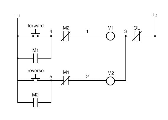
Interlocking Methods For Reversing Control Basic Control Circuits from www.industrial-electronics.com It shows the components of the circuit as simplified shapes, and also the power as well as signal connections in between the gadgets. Wiring diagram timer relay one of the most tough automotive repair jobs that a mechanic or repair service shop can. Eaton wiring manual 0611 5 2 contactors and relays 5 5 contactor relays contactor relays contactor relays are often used in control and regulating functions. Thus relay will be on for required amount of time set by the user using pot and then it is switched of automatically. The circuit that applies the voltage to the coil is referred to as the control circuit , because it controls the main device that the contactor or relay is switching. F delay timer wiring diagram best qd 253 post purge timer f. Contactor wiring guide for 3 phase motor with circuit breaker. The relay logic control works efficiently to perform basic on/off operations by opening or closing the relay contacts but it involves a humongous wiring.
Generally, control relays are intended for controlling relatively low current applications, more or less in the range of 300 va to 2000 va.
240 volts ac and 480 volts ac are commonly used for these large pieces of. Assortment of timer relay wiring diagram. A 12v relay is used to drive the ac load connected at the output. Thus relay will be on for required amount of time set by the user using pot and then it is switched of automatically. It shows the components of the circuit as simplified shapes, and also the power as well as signal connections in between the gadgets. The relay logic control works efficiently to perform basic on/off operations by opening or closing the relay contacts but it involves a humongous wiring. A contactor joins 2 poles together, without a common circuit between them, while a relay has a common contact that connects to a neutral position. Hence time t=120k*470uf=6 2 seconds~1 minute (approximately). The relays which are used after the manufacture of thyristors and triacs based on the semiconductor principle are still used in applications requiring very. Switching two relays at one time is like flipping 2 switches at once….with the same result. Timer has two element, timer and relay. With help of following timing diagram we can easily understand working of timer. F delay timer wiring diagram best qd 253 post purge timer f.
A wiring diagram is a streamlined traditional photographic representation of an electrical circuit. Power poles 3 pole reversing contactor set. Timer has two element, timer and relay. F delay timer wiring diagram best qd 253 post purge timer f. How to wire a contactor.
Motor Control Circuits Ladder Logic Electronics Textbook from www.allaboutcircuits.com The relay logic control works efficiently to perform basic on/off operations by opening or closing the relay contacts but it involves a humongous wiring. Time delay relays are simply control relays with a time delay built in. A contactor joins 2 poles together, without a common circuit between them, while a relay has a common contact that connects to a neutral position. Timer has two element, timer and relay. Pdf contactor wiring diagram with timer. These lines far exceed the 120 volts ac standard in most homes. At the same time, relays are able to control electrical and electronic circuits of many different characteristics by switching without being affected by different frequencies and wave types. Assortment of timer relay wiring diagram.
Time delay relays are simply control relays with a time delay built in.
A simple circuit diagram either of the two start buttons will close the contactor, either of the stop buttons will open the contactor. I have the contactor and timer sketch below, hope its clear enough. Wiring a single phase motor through a 3 phase contactor how and why. Operationally, it works the same way. Dol starter control and power wiring by using a fuse, contactor, overload relay, motor. Many large pieces of equipment are powered directly from high voltage lines. A contactor joins 2 poles together, without a common circuit between them, while a relay has a common contact that connects to a neutral position. Contactor wiring guide for 3 phase motor with circuit breaker. The circuit incorporates relays along with other components such as switches, motors, timers, actuators, contactors etc. 3 phase motor contactor/overload relay starter The relay logic control works efficiently to perform basic on/off operations by opening or closing the relay contacts but it involves a humongous wiring. At the same time, relays are able to control electrical and electronic circuits of many different characteristics by switching without being affected by different frequencies and wave types. In electrical engineering, a switch is an electrical component that can break an electrical circuit, interrupting the current or diverting it.